Damping factor effects on loudspeakers
Premise
Like many critical specifications in audio power amplifiers, damping factor often receives insufficient attention despite its profound impact on sound quality.
Damping factor significantly influences a speaker’s mechanical movement, potentially introducing distortion that conventional measurement techniques cannot detect. Standard testing methods—using constant test tones or simple frequency sweeps—fail to reveal how damping factor affects real-world musical reproduction. This parameter creates a complex relationship between amplifier and speaker that fundamentally shapes the resulting sound quality.
This discussion will explore in detail exactly how damping factor works and the specific ways speaker performance changes in response to different damping characteristics.
Loudspeaker basics
An ideal audio amplifier functions as a constant voltage generator with theoretical perfect specifications: infinite input impedance, unlimited speed, unlimited bandwidth, and zero output impedance.
Of these specifications, output impedance deserves special attention as it directly determines the damping factor—the relationship between an amplifier’s output impedance and the impedance of the connected speaker.
While achieving truly zero output impedance is physically impossible in real-world amplifiers, well-designed units can achieve very low values. This ensures acceptable signal quality with distortion that’s either inaudible or negligible compared to the inherent distortion of the speaker itself.
To understand how damping factor works, we need to first understand the basic mechanics of loudspeakers.
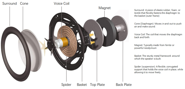
A conventional loudspeaker consists of four main components: a permanent magnet, a coil, a cone, and suspensions. The suspensions hold the coil centered in the air gap above the magnet, while the cone and suspensions are physically attached to the coil.
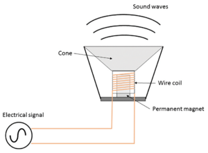
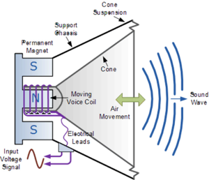
When electrical current flows through the coil, it creates a magnetic field that either aligns with or opposes the permanent magnet’s field, causing the coil to move toward or away from the magnet. Since the cone is attached to the coil, this movement pushes air, creating sound waves.
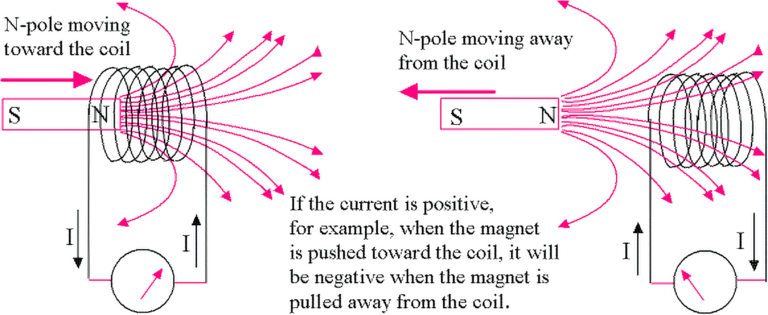
Importantly, a speaker is a bidirectional device. Not only can electricity create movement, but movement can create electricity. When the cone moves, it displaces the coil relative to the magnet, causing electrons in the coil to move in response to the magnetic field. This generates a small electrical current at the speaker terminals—essentially functioning like a solenoid, where a magnet moving inside an inductor creates voltage across that inductor.
Discovering the problem
If speakers were ideal components, their cones would stop moving the instant an audio signal ended. However, real-world speakers behave quite differently due to their physical construction.
A speaker consists not only of its magnetic core and voice coil but also includes a cone connected to the outer basket by elastic components—specifically a spider (the corrugated suspension at the voice coil) and a surround membrane at the cone’s outer edge.
These elastic components are designed to return the cone and voice coil to their neutral position when the input signal ceases. However, because they’re inherently springy, they create a mechanical oscillation—the cone doesn’t simply stop but rather bounces back and forth until various friction forces eventually bring it to rest.
This oscillatory behavior means the speaker continues to produce sound even after the electrical signal has stopped. The amplitude and duration of these unwanted oscillations depend on multiple factors: the amplitude of the original signal, how abruptly the signal stops, the stiffness of the suspensions, the mass of the cone, air density, and even the internal air compression within the speaker enclosure.
This continued movement of the speaker cone represents a form of distortion—when the electrical signal stops but the cone keeps moving, it continues pushing air and creating sound that wasn’t present in the original signal. Any sound produced after the electrical signal ends is, by definition, distortion since it doesn’t match the input.
While the example in the graph shows an extreme case, this phenomenon occurs constantly during music playback. Musical signals contain multiple overlapping frequencies that require the cone to frequently and abruptly change direction. The cone’s physical mass and the elasticity of its suspensions create inertia that resists these rapid directional changes.
This is precisely where damping factor becomes crucial. Damping factor represents the amplifier’s ability to control the speaker’s mechanical inertia and force it to follow the original signal more accurately. It works as a braking mechanism that helps prevent the cone from overshooting or continuing to move when it should stop.
To understand how damping factor controls speaker movement, we need to examine how an amplifier’s feedback network functions and how output impedance is calculated. Mathematically, damping factor is determined by dividing the speaker’s impedance by the amplifier’s output impedance.
An amplifier’s output impedance varies based on several factors, including the specific frequency being measured, the connected speaker’s impedance, and most significantly, the strength of the amplifier’s feedback system.
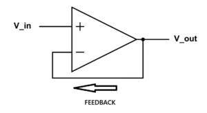
Since neither amplifiers nor speakers are ideal components, they inevitably introduce various forms of distortion. Feedback systems address this by continuously comparing the input signal with the output signal. These systems work by taking a portion of the output signal, inverting it (making it negative), and adding it back to the input. This creates a correction mechanism that helps produce a more accurate output signal.
Electronic devices employ different types of feedback. Local feedback operates within specific circuit sections using degeneration resistors or error correction systems. Global feedback is more comprehensive, enclosing the entire amplifier in a feedback loop by connecting the output back to a differential system at the input stage.
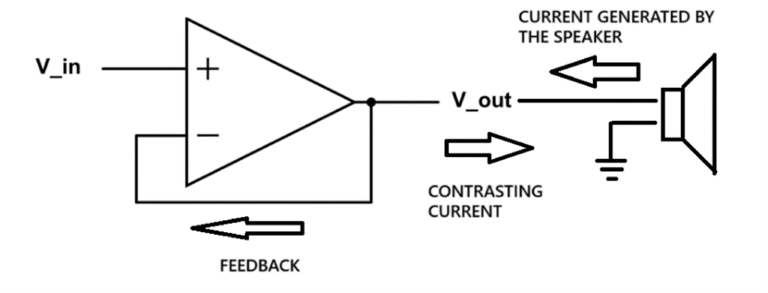
This feedback mechanism is the key to how damping factor controls speaker movement. When a speaker cone continues oscillating after the signal stops, it acts as a generator, producing a small electrical current at its terminals. This current flows back into the amplifier’s feedback system, which responds by generating an opposing current specifically designed to counteract and dampen these unwanted speaker oscillations.
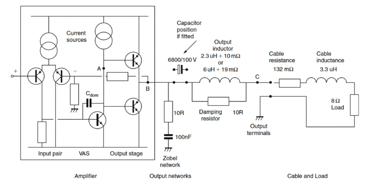
The effectiveness of this damping—represented by the damping factor—is primarily determined by the strength of the feedback system. However, everything between the amplifier’s feedback point and the actual speaker voice coil affects this relationship. This includes not just the amplifier’s output circuitry, but also binding posts, speaker cables, and especially passive crossover components in the speaker. All these elements increase the effective output impedance and consequently reduce the damping factor.
It’s important to note that speaker cable impedance must be calculated by summing both the positive and negative conductors, not just the positive wire. This means every component in the signal path—from amplifier output to speaker voice coil—reduces the effectiveness of the damping factor’s control over the speaker.
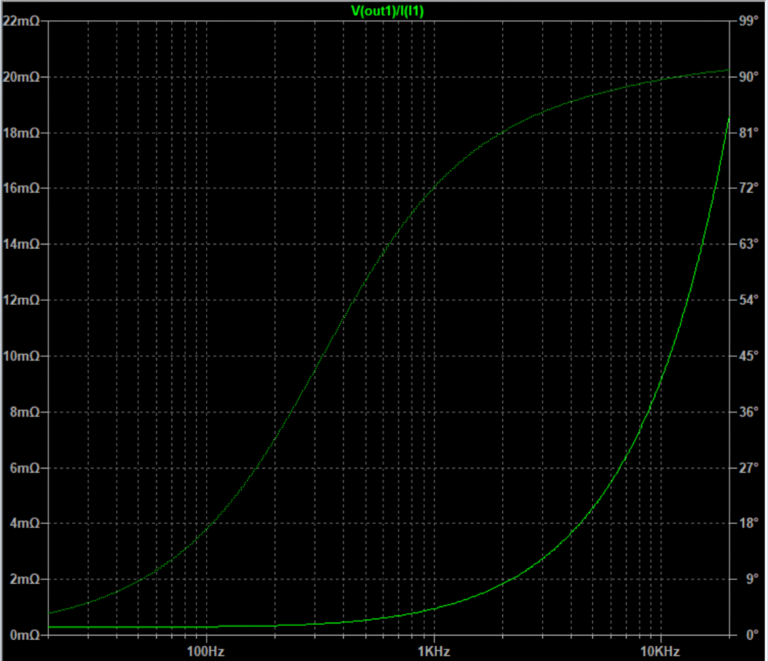
Additionally, an amplifier’s output impedance isn’t consistent across all frequencies. It typically increases as frequency rises, meaning damping factor decreases at higher frequencies.
While damping factor matters across the entire frequency spectrum, its effects become most noticeable in the bass range. This occurs because musical signals generally contain greater power in lower frequencies, causing larger cone excursions. With these larger movements, the controlling effect of the damping factor becomes far more audible.
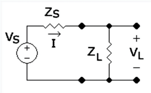
To demonstrate how damping factor influences speaker behavior, we can examine a simplified circuit model. For clarity, this model uses ideal components: the amplifier and load are considered perfect, with the load represented as a simple resistor rather than a complex speaker. This means any effects shown would be significantly more pronounced with an actual speaker. The model also excludes output networks, cable impedance, and crossover impedance to isolate the damping effect.
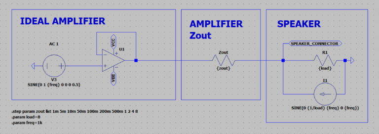
For this demonstration, we’ll use a simplified model with ideal components to clearly isolate the effects of damping factor. Instead of modeling a complex speaker with its mechanical and electrical characteristics, we’ll use a simple resistive load. This approach actually understates the problem—in real-world scenarios with actual speakers, these effects would be considerably more pronounced. We’re also excluding the additional impedances from output networks, speaker cables, and crossovers to focus solely on the damping mechanism.
The only variable in our simulation is the amplifier’s output impedance. Since an ideal amplifier would have zero output impedance, we’ll introduce different values using a resistor (Zout) placed after the feedback point. To simulate the speaker’s mechanical inertia, we’ve added a constant current generator flowing toward the amplifier, representing the reverse current generated by the cone’s continued movement.
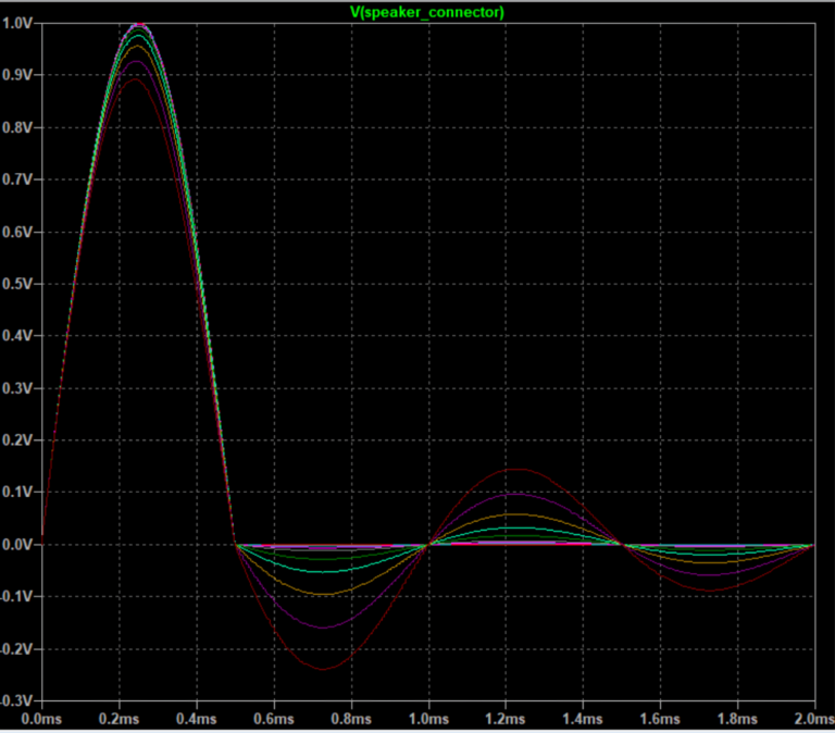
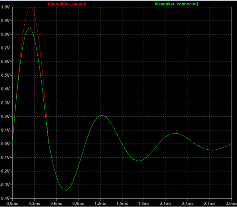
The simulation results reveal two important effects as output impedance increases (damping factor decreases):
First, the speaker’s ringing (unwanted oscillation after the signal ends) becomes more pronounced and lasts longer with higher output impedance.
Second, the original signal itself becomes distorted. This happens because the amplifier with higher output impedance can’t deliver sufficient power to overcome the speaker cone’s initial inertia. At the beginning of a signal (t=0), the cone resists movement, and an amplifier with poor damping struggles to force it into motion accurately.
A lower output impedance (higher damping factor) clearly maintains a signal that more faithfully reproduces the original input. The following measurements quantify these differences.
| Output impedance | Resulting damping factor | |
|---|---|---|
| 8 Ohm load | 4 Ohm load | |
| 1 mOhm | 8000 | 4000 |
| 5 mOhm | 1600 | 800 |
| 10 mOhm | 800 | 400 |
| 50 mOhm | 160 | 80 |
| 0.1 Ohm | 80 | 40 |
| 0.2 Ohm | 40 | 20 |
| 0.5 Ohm | 16 | 8 (almost no effect on load threshold) |
| 1 Ohm | 8 (almost no effect on load threshold) | 4 |
| 2 Ohm | 4 | 2 |
| 4 Ohm | 2 | 1 |
| 8 Ohm | 1 | 0.5 |
Here is a measured data from table, values are referred to 1 Vpk half sine wave with 0 seconds of decay time.
Overshoot voltage refers to the first, lowest, peak of the wave after the signal stops, the THD is the percentual of the signal distorted taking in consideration the overshoot voltage compared to the output signal (1 Vpk). The voltage attenuation is how much of the original signal is attenuated before arriving to the load.
| Load impedance | 8 Ohm | 4 Ohm | ||||
|---|---|---|---|---|---|---|
| Output impedance | Overshoot voltage | THD | Voltage attenuation | Overshoot voltage | THD | Voltage attenuation |
| 1 mOhm | 60 uV | 0.006 % | - 30 uV | 120 uV | 0.012 % | - 60 uV |
| 5 mOhm | 300 uV | 0.03 % | - 140 uV | 600 uV | 0.06 % | - 280 uV |
| 10 mOhm | 600 uV | 0.06 % | - 270 uV | 1.2 mV | 0.12 % | - 540 uV |
| 50 mOhm | 3 mV | 0.29 % | - 1.4 mV | 6 mV | 0.58 % | - 2.8 mV |
| 0.1 Ohm | 6 mV | 0.59 % | - 2.7 mV | 12 mV | 1.18 % | - 5.4 mV |
| 0.2 Ohm | 12 mV | 1.16 % | - 5.4 mV | 24 mV | 2.32 % | - 10.8 mV |
| 0.5 Ohm | 28 mV | 2.81 % | - 13 mV | 56 mV | 5.62 % | -26 mV |
| 1 Ohm | 53 mV | 5.30 % | - 26 mV | 106 mV | 10.6 % | -52 mV |
| 2 Ohm | 96 mV | 9.66 % | - 44 mV | 192 mV | 19.32 % | - 88 mV |
| 4 Ohm | 160 mV | 16 % | - 72 mV | 320 mV | 32 % | - 144 mV |
| 8 Ohm | 240 mV | 24 % | - 100 mV | 480 mV | 48 % | - 200 mV |
The level of distortion can reach enormous proportions when insufficient damping factor fails to properly control speaker movement.
For optimal performance, damping factor should be as high as possible. This becomes especially critical when speaker impedance drops, which causes distortion to increase dramatically.
But the problems extend beyond simple distortion. Another significant consequence of reduced damping factor is the deterioration of the speaker’s frequency response linearity. Since damping factor essentially represents how much control the amplifier exerts over the speaker, when this control becomes too weak, the system’s actual frequency response becomes increasingly dominated by the speaker’s own impedance characteristics.
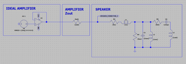
Taking for example a circuit where the speaker is now a real-world one, the impedance module now is non-linear.
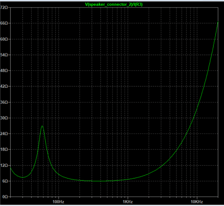
The frequency response becomes subject to the speaker impedance the higher the amplifier output impedance.

Here is another real-word computation: effects of amplifier damping factor on the frequency response when connected to a simulated impedance load typical of a two-way closed box loudspeaker system.
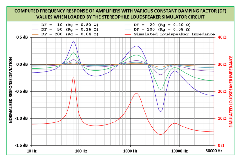
Even implementing a Zobel network—a circuit commonly used to flatten a speaker’s impedance curve—doesn’t fully resolve these issues. While a Zobel network can help linearize the speaker’s impedance, two major frequency response problems persist with low damping factors: overall bandwidth becomes attenuated, and a pronounced deviation occurs around the speaker’s resonant frequency (Fs). These frequency response anomalies simply don’t appear when the amplifier’s output impedance is sufficiently low.


Using passive crossovers significantly worsens these damping issues, fundamentally altering the frequency response that designers carefully engineered. What should be a precisely controlled frequency division becomes unpredictable when damping factor is compromised.
Even when an amplifier features exceptionally low output impedance, every passive component in a crossover network adds its own impedance to the circuit. As crossover complexity increases, this added impedance accumulates. Consider even the simplest low-pass filter consisting of just a single inductor—standard commercially available inductors rarely have impedances below 0.5 ohms, which is remarkably high in this context.
To put this in perspective: adding a 0.5 ohm inductor to an 8-ohm speaker system immediately reduces the effective damping factor by 16 times, even with a theoretically perfect amplifier. This single component dramatically degrades the amplifier’s ability to control speaker movement.

In the simulation, a Zobel network is used to linearize the impedance module of the speaker and is used an ideal inductor with zero impedance, only variating the Zout.
This shows that even with a perfect crossover calculation, the bandwidth changes significantly depending on the amplifier used.
Conclusions
This investigation makes clear that conventional measurement techniques—using simple frequency sweeps or constant test tones—cannot adequately reveal damping factor distortion. These standard tests would only show signal attenuation rather than the complex distortion mechanisms at work.
By using pulsed test signals instead, we can properly observe speaker excursion behavior and accurately assess how damping factor affects performance. This approach reveals that insufficient damping produces remarkably significant distortion and can substantially alter a speaker’s frequency response characteristics.
These findings underscore the critical importance of minimizing impedance in everything between the amplifier’s feedback point and the speaker’s voice coil. Particular attention should be paid to amplifier output networks and excessively thin speaker cables, both of which can compromise damping performance. For optimal results, eliminating passive crossovers entirely and adopting multi-amplification with active crossovers represents the most effective solution to maintain proper damping control throughout the audio spectrum.