Slew rate effects on audio
Premise
Slew rate in electronics refers to how quickly an electrical signal can change over time. Specifically, it measures the maximum rate of change of voltage, current, or other electrical quantities. This property is typically expressed in units per second – most commonly volts per microsecond (V/μs) in technical documentation and component datasheets. The concept is important when evaluating how rapidly electronic components can respond to changing input signals, particularly in applications requiring fast signal processing.
Slew rate represents one of the most significant parameters in electronics, particularly in audio power amplifiers where it stands among the three most critical specifications alongside distortion measurements and damping factor (output impedance).
Despite its importance, slew rate often receives insufficient attention. Historically and for marketing purposes, Total Harmonic Distortion (THD) has dominated discussions about amplifier quality, becoming the primary concern for many consumers when selecting equipment.
This narrow focus has created a division within the audio community. One group places complete faith in amplifiers with extremely low distortion figures, while another has grown skeptical of measurements altogether. The latter group observes that amplifiers with similar distortion specifications can produce noticeably different sounds and handle speaker loads differently.
For those who prioritize their listening experience over specifications, distortion measurements gradually lose credibility. This can lead to an unfortunate rejection of scientific measurement entirely, sometimes resulting in belief in pseudoscientific solutions like exotic cables or grounding devices filled with sand.
The core issue stems from inadequate education about audio measurements. Though scientific understanding and measurement-based approaches are slowly gaining ground, progress remains gradual.
A fundamental truth in audio engineering is that no single parameter can fully characterize an amplifier’s performance with various input signals or output loads. Multiple specifications must be considered together. Among these, slew rate deserves particular attention.
How slew rate changes the audio signal
Slew rate applies to signal processing in all electronic components, whether active (amplifiers, operational amplifiers) or passive (crossover networks). When a signal passes through any electronic device, the output signal speed invariably decreases compared to the input signal speed. This reduction represents a fundamental principle in physics – similar to how efficiency cannot exceed 100%. The output signal speed can never exceed the input signal speed.
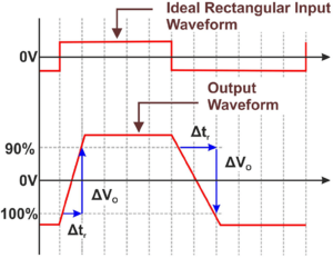
In audio applications, slew rate measurement involves introducing a square wave signal into the device under test. The calculation is performed by dividing the amplitude (measured in volts) by the rise time or fall time of the square wave (measured in seconds). This provides the rate of voltage change per unit time.
The measured slew rate varies significantly depending on the connected load. When load impedance decreases, the slew rate typically decreases as well. This occurs because lower impedance creates greater current demand, which affects the device’s ability to change voltage quickly across the load.

The reduction in output signal speed inherently represents a form of signal distortion. This alteration in signal shape occurs universally across electronic devices, as no component can achieve perfect signal transmission without some degree of modification. Every device introduces some level of distortion; complete neutrality remains theoretically impossible.
The critical consideration becomes determining acceptable distortion thresholds for different applications and components. This raises an important question: how much Total Harmonic Distortion plus Noise (THD+N) can a device produce before becoming audibly detectable or significantly altering the signal?
The answer varies depending on the specific device and its position in the audio chain. For audio source components (such as digital-to-analog converters or preamplifiers), extremely low distortion levels are essential. Achieving THD+N measurements below 0.005% becomes necessary for such devices, as these components establish the foundation of the entire audio reproduction chain. Any distortion introduced at this stage propagates through subsequent components.

In the example above, the signal is amplified and passed through a resistive load. The final distortion of the operational amplifier is very low anyway. In the second circuit, a source of 100uV of a second signal is introduced to simulate the distortion of 0.01% from the source. The final distortion is amplified as much the signal is amplified and then the device distortion is added.

Distortion represents only part of the audio quality equation. Noise creates an equally significant concern, as both distortion and noise from the source component become amplified by subsequent stages. This compounding effect means that source noise contributes to the total noise floor, which then combines with additional noise generated by the amplification stages.
This relationship creates a critical distinction: while low-level distortion might remain imperceptible, the same distortion at higher amplification levels can substantially degrade sound quality, create unwanted artifacts in speaker movement, and elevate background noise. These effects underscore the importance of using low-distortion equipment throughout the signal chain, with source components demanding particularly stringent performance.
The audio industry lacks universally standardized thresholds for acceptable distortion levels or human perception limits. This absence stems from significant variation in distortion sensitivity among listeners.
Despite this, the Compact Disc format often serves as a de facto reference standard: 16-bit depth provides a 96dB dynamic range with theoretical THD of approximately 0.0015%. At these performance levels, both distortion and noise typically fall below the threshold of audibility for virtually all listeners.
Regarding signal speed reduction, a critical question emerges: what minimum slew rate prevents signal distortion? For sinusoidal waveforms, this calculation is relatively straightforward:

Depending on the frequency, you need a certain quantity of output speed to reproduce that frequency perfectly. In electronics the slew rate is nothing other than the maximum speed with which the signal can vary. For this reason, bandwidth and slew rate are two things that go hand in hand. If a device can reproduce a certain frequency, it means that it has sufficient speed to do so: it means also that the higher the frequency the higher the slew rate required.

In the example above, is calculated the slew rate required to reproduce a 20kHz sine wave or rather the maximum audible frequency. It means, that for each output Volt is required a slew rate of 0.125V/us to not distort the signal.
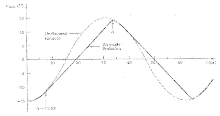
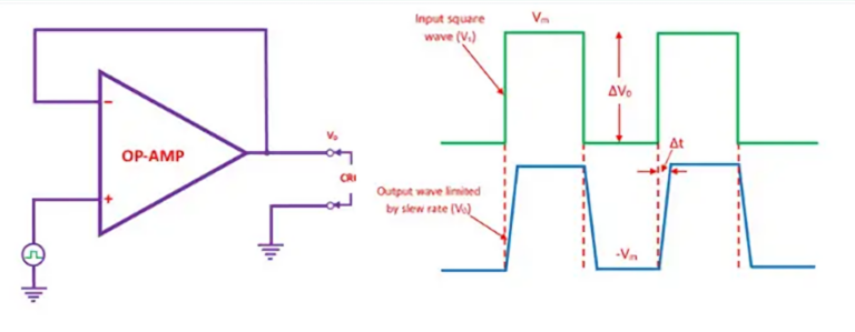
When slew rate proves insufficient for reproducing sinusoidal signals, distortion occurs. The waveform becomes compressed in both amplitude and frequency (appearing as longer periods in the time domain) and gradually transforms into a triangular wave. This transformation effectively reduces the device’s total bandwidth.
Consider a practical example: a power amplifier driving a standard 8Ω load at 100W requires approximately 28V RMS output voltage. Since alternating current flows in both positive and negative directions, the peak-to-peak voltage (Vpp) reaches 56V. Slew rate calculations must account for this complete voltage swing.

For this amplifier to reproduce a 20kHz signal at 56Vpp without distortion, it requires a minimum slew rate of 7V/μs. This calculation applies specifically to sinusoidal signals.
Slew rate requirements therefore depend directly on both output voltage and maximum frequency. These factors together determine what engineers call “power bandwidth” – the frequency range a device can reproduce at a specified voltage level without distortion.
This concept often creates confusion when evaluating audio amplifiers. An amplifier’s effective bandwidth is not constant across all output voltages. As output voltage increases, the maximum frequency the amplifier can reproduce without distortion decreases.

To simulate a slew reduction, an inductor is introduced

As shown, the resulting bandwidth is directly affected by the lack of slew rate, and vice versa.

In this example, there are two identical circuit, but in the second one the input voltage is 10 times larger. As shown by the graph, the output of the first circuit has the correct amplitude and the wave is undistorted. Meanwhile, the second voltage (same frequency) has reduced amplitude and distorted to a triangle wave. This is clearly a demonstration on how the output voltage interfaces with the maximum speed of the amplifier: the higher the voltage, the lower the reproducible bandwidth.
For the maximum bandwidth an amplifier can have at a certain output voltage, is possible to use the inverse equation for the slew rate:

Class D amplifiers provide an excellent illustration of bandwidth limitations in audio equipment. These switching amplifiers filter their output square waves to produce sinusoidal signals, a process that inherently reduces signal speed and output bandwidth. In poorly designed switching amplifiers, this bandwidth reduction can become excessive.
High-quality class D amplifiers typically maintain a flat frequency response from 20Hz to 20kHz, with minimal attenuation (approximately -0.5dB) above 20kHz. This performance appears ideal from an audio perspective, as such amplifiers reproduce all frequencies within the standard audible range with equal intensity.


A flat frequency response extending to 20kHz, while seemingly adequate, proves insufficient for high-quality audio amplification. This specification overlooks a critical factor: signal speed.
The output filtering in class D amplifiers creates frequency shifts when cutoff points lie too close to the audible band. This filtering substantially reduces maximum signal speed at the load, limiting slew rates to approximately 12-14V/μs even in premium class D amplifiers.
This limitation doesn’t affect all class D designs equally. The primary determining factor is the location of the feedback sampling point. Amplifiers that take feedback after their LC filter network (representing the majority of commercial designs) experience these slew rate constraints. Alternative feedback arrangements can preserve higher slew rates.
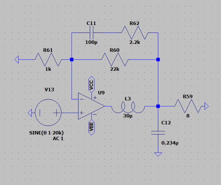
This is a simplified schematic of an amplifier with its feedback point after the LC filter.
As long as the feedback factor is greater than one (i.e. for frequencies below the unity-gain point of the feedback loop) an amplifier shows a frequency response which is approximately the inverse of the feedback network’s frequency response.
With the feedback point placed in this way, the LC filter will force the overall amp to behave like a first order lowpass. If the slew demand increases (increases the input frequency and amplitude) the NFB will force the modulator/output stage into transient saturation while trying to emulate the lowpass response of the overall amplifier, thus lowering the output slew.

Even using an ideal amplifier with infinite slew and output current, the maximum rise/fall time of the wave and the amplitude is strongly decreased.
Talking about measured real data, with a slew between 10 and 14V/us, and picking the maximum audible frequency, 20kHz, the maximum output voltage with undistorted signal is about 111V, meaning (divided by positive and negative swing) 55.5V, or 385W on 8 Ω.
Surely a pretty high power, but this means that even the best class D amplifiers cannot reproduce 20kHz at their maximum power: both because maximum power can be over 2000W and because there are no more (or equally) precise class Ds with wider bands than these.
However, this ONLY:
- IF the slew is actually this high, because many of the times the measured slew at that bandwidth is no more than 10-11V/us. In low and mid quality class D amplifier the slew is no more than 2-3V/us, meaning a power bandwidth of only 8.5kHz at 100W output, and standard linear amplifiers no more than 5-7V/uS.
- IF we are talking only about sinusoids, because the required slew to reproduce a square wave is much greater.
- IF we are calculating a single sine wave.
The calculations were only for a single sinusoid, but in audio, we will not have a single signal. Any audio signal can be represented as a sum of sinusoids, in a given delta time there could even be over 10 different signals, at different amplitudes.

For example, a square wave, that is a very simple signal, is a sum of the fundamental frequency plus all his odd harmonics with a slope of 8dB/oct.
Using a central frequency of 1kHz we calculate the slew rate required for each volt of a square wave:
| Frequency | 1 kHz | 3 kHz | 5 kHz | 7 kHz | 9 kHz | 11 kHz | 13 kHz | 15 kHz | 17 kHz | 19 kHz |
|---|---|---|---|---|---|---|---|---|---|---|
| Level | 0 | -9.5 dB | -14 dB | -16.9 dB | -19.1 dB | -20.8 dB | -22.3 dB | -23.5 dB | -24.6 dB | -25.6 dB |
| Voltage | 1 | 0.335 | 0.2 | 0.143 | 0.111 | 0.091 | 0.077 | 0.067 | 0.059 | 0.052 |
| Required Slew (V/uS) | 0.0063 | 0.0063 | 0.0063 | 0.0063 | 0.0063 | 0.0063 | 0.0063 | 0.0063 | 0.0063 | 0.0063 |
A simple sine wave of 1 volt at 1kHz of frequency require only 0.0063V/us of slew rate. A square wave, is a sum of the odd harmonics to a fundamental frequency. In the table we consider only harmonics below 20kHz (the ones that will reach the ear), the required slew is calculated by multiplying each harmonic base required slew with actual voltage.
As we can see, the required slew is constant for each harmonic, so we can summarize in:

Where “h” is the number of odd harmonics to consider (all before 20kHz). If we sum all the required slew values, we obtain that a square wave of 1kHz frequency and with amplitude of 1V require 0.063V/us. Which seems like little, but it’s actually 10 times the value needed for a sine wave.
This means that for a 100W output on a 8 Ω load the slew required will be then 3.5V/us, in the case of a single sinusoid it would barely be 0.35V/us.
Now, this is what happens with a simple square wave, but the slew required for a real music signal is even higher.

In a real audio signal, the number of intermodulated signals and their amplitude is unpredictable. There could even be over 20 different signals intermodulated at the same time.
Now arrives a difficult step to understand: as for test, if we added the slew required for each single frequency from 1kHz to 20kHz, jumping 1kHz at a time, all at the same amplitude we would obtain 1.323V/us of required slew (required slew for voltage of 1kHz + 2kHz + … + 20kHz).
The output voltage for each signal is exactly 1V, intermodulating those signals we obtain a complex wave of about 1V.

The slew rate requirements for undistorted output scale directly with voltage. Each volt of output requires approximately 2.646V/μs of slew rate capacity in each direction (positive and negative).
Applying this to the previously discussed class D amplifier with a maximum slew rate of 14V/μs reveals significant limitations. This amplifier could only produce 5.29V of undistorted output, which translates to merely 3.5W into an 8Ω load before generating slew-induced distortion and unwanted harmonics.
For the 100W output example (requiring approximately 28V RMS), the necessary slew rate climbs to roughly 74V/μs. This value exceeds the capabilities of over 90% of commercially available amplifiers, highlighting a widespread performance limitation in the market.
Instead of the conventional approach using numerous individual test tones, a more practical analysis can be performed using just 8 intermodulated waves.

In the simulation is used a universal ideal amplifier, without any load and at unitary gain, capable of amplifying with zero distortion: because we need to isolate the effects of the lack of slew.

Applying about 28V of voltage at the input (corresponding at 100W on 8 Ω load), 8 fundamentals (1, 2.5, 6.5, 8.5, 13, 14, 17, 20kHz): the resulting slew required to amplify those sinusoids at that specific amplitude is about 26V/us, the amplifier maximum slew is 60V/us (as the slew of KRIEG Nemesis V1 and V2), the resulting distortion is negligible (-110dB).

Using same parameters, downgrading the maximum amplifier slew to 14V/us (as the slew of one of the lowest distortion class D amplifier), obtaining a resulting distortion of -65dB (0.056%): 180 times higher than the amplifier with 60V/us of slew rate.
This test excludes any possible distortion introduced by the sources and the amplifier, even excluding the load, demonstrating how the slew actually has a heavy and serious impact on the final distortion performance. This case is definitely a real case, the quantity of simultaneous signals is very low, and despite this the performances are strongly degraded.

Another test, made just for fun, with a slew of 800V/us, but demonstrates that if the slew is indefinitely high, then the distortion would be zero.
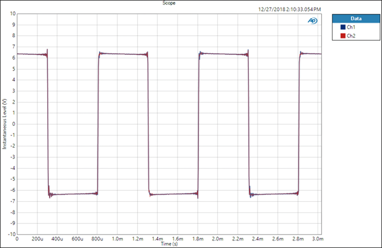
Real measurement demonstration of distortion induced by low slew of an amplifier:

Conclusions
This analysis demonstrates a critical principle in audio engineering: amplifiers that measure perfectly in terms of distortion when reproducing simple sinusoidal test tones can nevertheless produce substantial distortion when processing complex waveforms like music. Standard distortion measurements fail to capture this real-world performance limitation.
The mathematical and experimental evidence establishes slew rate as a parameter of equal importance to traditional Total Harmonic Distortion measurements. Higher slew rate values directly correlate with an amplifier’s ability to reproduce complex signals without introducing slew-induced distortion. This specification deserves careful consideration when evaluating audio equipment, particularly for high-fidelity applications where accurate reproduction of complex musical passages is essential.