Passive crossover problems in audio
Premise
A passive crossover is a circuit made of components like coils (inductors), capacitors, and resistors that sits between your power amplifier and your speaker. Think of it as a gatekeeper that comes after the amplifier but before the sound comes out.
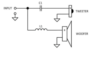
The main job of this circuit is to filter frequencies – allowing only certain ranges of the audio signal to pass through to specific speaker drivers. For example, sending low frequencies to a woofer and high frequencies to a tweeter. In some designs, it also helps smooth out the frequency response across the entire range.
Active crossovers, by contrast, perform similar filtering functions but are placed earlier in the audio chain – before amplification or even at the source level.
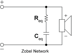
Not all passive component networks connected to speakers qualify as crossovers. For instance, a Zobel compensation cell uses passive components but doesn’t actually split frequencies. Instead, it works to stabilize the speaker’s impedance (electrical resistance), making it more consistent across different frequencies.
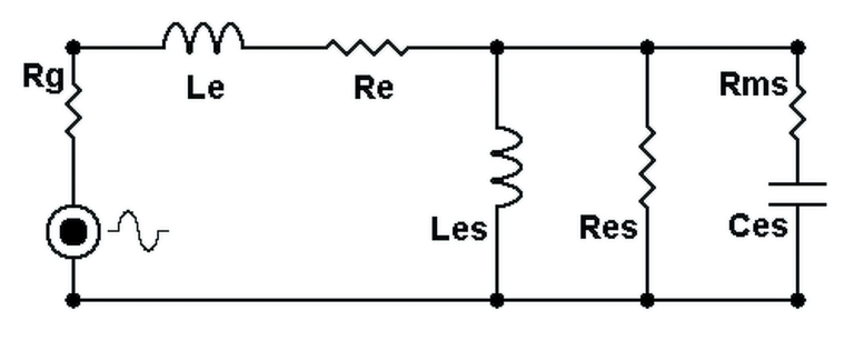
Loudspeakers are electrically sophisticated devices – they don’t simply accept electrical signals in a straightforward way. Instead, they behave like complex networks of electronic components (inductors, capacitors, and resistors) all working together.
What’s particularly concerning about passive crossovers is that their fundamental problems would cause issues even if speakers were simple resistive loads – which they definitely are not. Throughout this analysis, will be used both actual measurements from real equipment and computer simulations to demonstrate these issues.
For the simulated tests, will be used perfect electronic components and simplified the speaker as a basic resistive load. This is important to understand because real-world conditions are significantly worse than what these simulations show. Actual electronic components have manufacturing variations and unwanted side effects, while real speakers present much more complex electrical behaviors.
The problems with passive crossovers are numerous and significant. These include increased audio distortion, reduced transient response (speed), decreased damping (correction factor), uneven frequency response with peaks and dips, shifted audio phase relationships, and inconsistencies due to component tolerance variations. This list only scratches the surface of the issues.
Problems [1]: reduced damping factor
The effects of damping factor are better described in the article “Damping factor effects on loudspeakers”.
The output impedance of an amplifier plays a crucial role in determining audio quality, and ideally should be kept as low as possible. This electrical characteristic directly relates to what audio engineers call the “damping factor.”
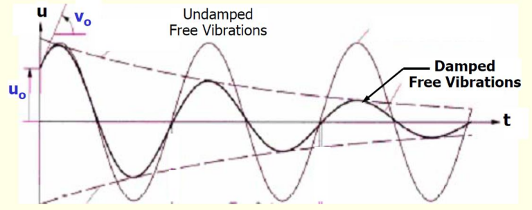
When an amplifier has low output impedance, it maintains better control over the speaker’s movement. This is especially important after the amplifier sends a signal and needs the speaker cone to stop moving precisely. A higher damping factor (resulting from lower output impedance) allows the amplifier to better control unwanted speaker motion, reducing distortion and improving accuracy in sound reproduction.
Think of it like a car’s braking system – an amplifier with high damping factor (low output impedance) provides precise stopping power for the speaker, preventing it from continuing to vibrate when it shouldn’t. This translates to tighter bass response and cleaner overall sound, particularly with dynamic music passages.
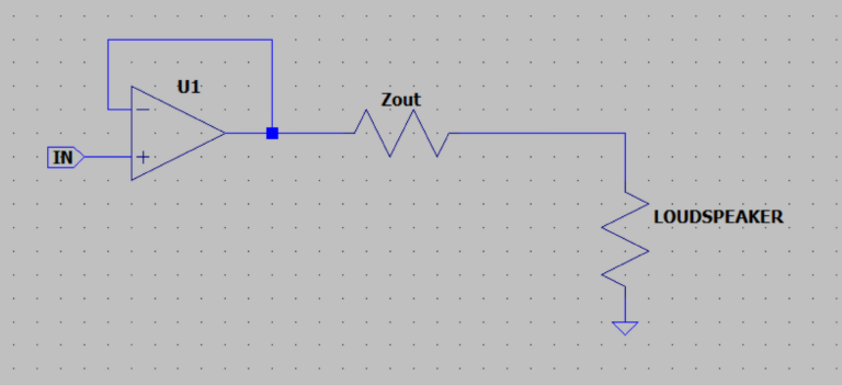
It’s essential to understand that damping factor decreases whenever impedance increases anywhere along the path between the amplifier’s feedback point and the speaker’s voice coil.
An important clarification: the damping factor isn’t just affected by what’s between the amplifier’s output terminals and the speaker box. It includes all impedance present from the amplifier’s internal feedback point (which is before its output terminals) all the way to the speaker’s voice coil itself.
This means every component in this chain adds impedance: terminal connections, speaker cables (including the return path), and most significantly, any passive crossover network.
A passive crossover substantially reduces or can nearly eliminate an amplifier’s damping factor by introducing considerable impedance between the amplifier and speaker. For perspective, even high-quality commercial inductors rarely have impedance below 0.5 Ohm. This is because achieving necessary inductance values without using magnetic cores requires many turns of wire, which inherently adds resistance.
To illustrate the impact: even with an excellent amplifier having a damping factor of 10000, adding a typical crossover inductor would drop the effective damping factor to merely 16 with an 8 Ohm speaker.
Additionally, an amplifier’s output impedance naturally rises as the connected load impedance falls. This means speakers with lower impedance ratings (like 4 Ohm vs 8 Ohm) experience even worse damping factor reduction than the theoretical halving you might expect.
In audio reproduction, damping factor is particularly critical for low frequencies, where speaker cones are more susceptible to unwanted oscillation. As damping factor decreases, bass becomes less controlled, resulting in loose, imprecise low-frequency reproduction. These effects are well-documented in audio engineering literature through extensive measurements.
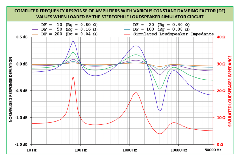
When damping factor decreases, it not only affects bass control but also reduces the linearity of a speaker’s frequency response. The damping factor essentially represents how much control the amplifier has over the speaker’s movement.
If this control becomes insufficient due to a low damping factor, the speaker’s frequency response becomes increasingly dominated by its own impedance characteristics. This means that instead of reproducing all frequencies evenly as intended, the speaker’s output will follow the natural peaks and dips of its impedance curve.
Think of it this way: with high damping factor, the amplifier maintains authority over the speaker, forcing it to follow the input signal accurately. With low damping factor, the speaker gains more independence, responding based on its own mechanical and electrical properties rather than purely following the amplifier’s instructions.
The result is an uneven frequency response where certain frequencies are emphasized or diminished not because of the recording, but because of how the speaker’s impedance naturally varies across different frequencies. This creates coloration in the sound that wasn’t present in the original material.
Problems [2]: artifacts in frequency response
A crossover’s primary function is to separate audio frequencies – directing different frequency ranges to appropriate speaker drivers. When working with a simple resistive load in theory, basic components like inductors and capacitors can create clean, predictable filters.
For example, a high-pass filter should cleanly allow frequencies above a certain cutoff point to pass through while blocking lower frequencies. This works perfectly in textbook scenarios.

However, real-world speakers don’t behave like simple resistors. Their electrical and mechanical properties create a much more complex system that includes varying impedance across frequencies, resonances, and inductance effects from the voice coil.
Because of this complexity, when you apply a seemingly straightforward crossover filter to an actual speaker, the results often deviate significantly from the ideal mathematical model. The frequency response becomes less predictable, with unintended peaks, dips, and phase issues that can compromise sound quality. What works perfectly in theory often produces problematic and imprecise results when implemented with real speakers.

Let’s take the frequency response of an example loudspeaker, and apply a simple high-pass capacitor to it.

The dotted line corresponds to the frequency response of the original speaker, the continuous line the resulting one after the filter has been added. The blue line, on the other hand, represents its impedance module.
As you can see, the slope is present, but above all, that the result is not what we expected: in fact, there is no constant attenuation, and there is a peak on the resonant frequency of the speaker.
Now let’s say to increase our cut, also applying an inductor, and varying the cut slope from 6dB/oct to 12dB/oct.

Thanks to a higher slope, now our crossover works almost well. However, the entire remaining frequency response has been changed. Now our loudspeaker is no longer linear, or rather, much less so than before.
Problems [3]: tolerances
All electronic components sold commercially have manufacturing tolerances, including the capacitors, inductors, and resistors used in crossovers. These tolerances represent the potential variation from the stated value.
Consider a simple simulation of a high-pass filter using a 100μF capacitor with a standard 10% tolerance connected in series with a resistor. This tolerance means the actual capacitance could range anywhere from 90μF to 110μF.
The consequences of this variation are significant: even when using completely identical amplifiers and speakers in two separate systems, the resulting frequency response will never be exactly the same between them. One system might begin rolling off bass at 80Hz while its seemingly identical twin might start at 88Hz.
These inconsistencies mean that carefully engineered speaker designs can’t perform exactly as intended once manufactured, as each individual crossover will behave slightly differently due to the cumulative effect of component tolerances. This creates unpredictability in the final sound signature, even among speakers of the same model.

Capacitors typically come with 10% tolerances as standard, which would be considered high for resistors, but is actually optimistic for inductors, which often have even wider manufacturing variations. These tolerances inevitably create channel-to-channel differences of several decibels at crucial crossover points.
While theoretically you could carefully select and match components to minimize these variations initially, this solution is temporary at best. Component values drift with changes in operating voltage, current flow, and especially temperature. This means even a perfectly matched crossover will develop inconsistencies during normal use.
It’s also important to recognize that loudspeaker drivers themselves have inherent manufacturing tolerances – no two drivers, even from the same production batch, are exactly identical in their performance characteristics. However, adding a passive crossover with its own tolerance issues compounds these variations significantly, effectively multiplying the inconsistencies rather than just adding them.
This compounding effect means that any careful engineering done at the design stage becomes progressively compromised as tolerances stack up through the signal chain, resulting in unpredictable performance variations between channels and between individual speaker systems of the same model.
Problems [4]: phase shifts
Considering the loudspeaker taken alone, and placed in half space (infinite baffle), we obtain from it two phases: one acoustic and one electric.
The first is related to its frequency response.
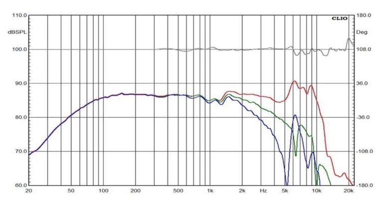
While the colored lines represent the frequency response at different angles, the gray line represents the phase of this frequency response. As you can see, the phase does not vary much during the speaker’s usable band.
The second phase, on the other hand, the electrical one, is linked to the speaker impedance module.
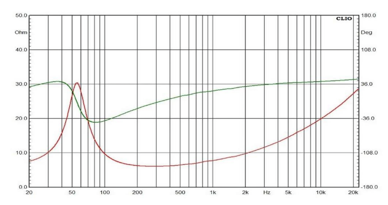
The blue line represents its impedance module, while the pink one represents the electrical phase. As you can obviously see, the electrical phase of a loudspeaker is not very linear. However, there are systems to linearize it, such as, for example, Zobel compensation cells.


After the application of a Zobel cell, the speaker impedance module is linearized, and consequently its phase. Which unfortunately, however, remains curved in the area of the resonant frequency.
Phase follows always the bandwidth in the theory of the signals, if a there is a cut-off frequency, there is a phase change.


A passive crossover is no exception, as is an active one: the variation of the electrical phase is inevitable when making a frequency cut.
Problems [5]: Performance and specs changing in current and temperature rising
Electronic components don’t maintain perfectly consistent performance under all conditions – this is a fundamental principle in electronics. The characteristics of resistors, capacitors, inductors, and other components change as operating conditions vary.
Specifically, both the amount of current flowing through a component and its temperature significantly affect how it performs. These variations aren’t random or unpredictable – manufacturers measure and document them. You’ll typically find these specifications expressed as “parts per million per degree Celsius” (ppm/C°) in the component’s datasheet. This tells you exactly how much a component’s value will drift as temperature changes, allowing engineers to account for these variations in their designs.
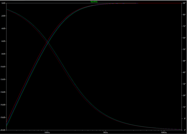
When electrical current flows through a component, it inevitably generates heat due to the component’s inherent electrical resistance. As this heat builds up and the component’s temperature rises, its electrical properties begin to change. Simulation results clearly show that the same crossover component produces noticeably different frequency responses at various temperatures (10°, 30°, and 60° Celsius).
Electrolytic capacitors are particularly sensitive to operating conditions. Their performance characteristics change significantly depending on the voltage applied across them, the amount of current flowing through them, and the frequency of the signals they’re handling – all in addition to temperature variations. These factors cause their actual capacitance value to drift from what’s printed on the label.
While other types of capacitors (film, ceramic, etc.) generally offer more stable performance, they still exhibit similar behavior, albeit to a much smaller degree. No capacitor maintains perfectly consistent specifications across all operating conditions.
Problems [6]: Added distortions
A crossover filter induces various types of distortion:
- Distortion due to frequency cut (slew distortion)
- Distortion due to the passage of the signal through the components
- Memory distortion
- Hysteresis distortion
Passive crossovers introduce several forms of distortion beyond just filtering frequencies. These include slew distortion (related to frequency filtering), component-induced distortion (from the signal passing through physical components), memory distortion, and hysteresis distortion.
To better understand how a passive crossover distorts rather than simply attenuates signals, consider what happens when a square wave passes through a low-pass filter. By definition, a low-pass filter must reduce the speed at which electrical current changes to function properly. This reduction in speed results in higher frequencies being attenuated. Bandwidth and speed are inseparable – when you reduce available bandwidth, you necessarily reduce signal speed.
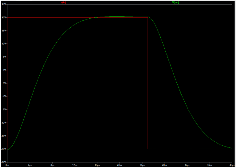
When examining the output signal, we can observe that the crossover doesn’t just cleanly reduce certain frequencies – it actively distorts the original signal. This speed reduction effect is technically called “slew induced distortion” and appears in both crossovers and switching amplifiers.
While the square wave example makes this distortion obvious, similar signal degradation occurs with all audio signals passing through a crossover. The distortion becomes more pronounced as the signal frequency moves away from the crossover’s cutoff frequency, especially outside the passing band.
Additionally, simply routing a signal through any electronic component increases both noise and distortion in the final output. Capacitors are particularly notorious for this effect.


As can be seen from the measurements, using the exact same signal with the exact same load, two different capacitors have two different distortions simply changing the dielectric type.
Note that, in this case, the load had a high impedance, and the current flow was therefore minimal. Despite this, even the MKP type capacitor (often used in passive crossovers) introduces its own distortion, which increases, and by a lot, with increasing voltage and current.
By placing an ideal inductor on a resistive load, the distortion of a simple sinusoid is theoretically zero. However, when the component becomes real, its variables strongly affect the signal. The distortion comes from the signal passing through the component itself, not from the cutoff frequency or even from slew-induced distortion.

Memory distortion is yet another type of distortion introduced by electronic components. It consists of signal-induced thermal drifts.
The circuit memory is the ability of a circuit to remember the past states of a signal. Here are some examples of memories:
- A capacitor: has memory, it integrates current into voltage
- An inductor: has memory, it integrates voltage into current
If we were to listen to music through this, however, we would notice that, after several seconds of low amplitude signals, the cap has discharged and will completely clip the crescendo that follows. This circuit has memory: the cap voltage is an image of past amplitude peaks.
In addition to the memory effect, at the passage of a non-constant signal we also have the variation of the temperature and of the current through the component, and therefore the variation of the electrical characteristics of the component itself. This, added to the component’s own distortion, creates enormous distortion damage.
Passing on, hysteresis distortion is a type of distortion that happens only when an inductor does have a magnetic core. It has always been known in the world of electronics and signals, and lately it is much discussed in the world of class D amplification.


The figure above highlights the issue. The signal traverses the B-H curve in each direction as given in the graph. The flux (and thus the voltage) at a specific point on the curve can be different depending how you arrive at that point. For instance, following the path 5 to 7 takes you through point 6, and although points 5 and 7 are identical on the B-H curve, the voltage at that point is not. The same situation occurs when you go from 2 to 4 through 3; the voltage values at identical points 2 and 4 are different depending on the path you took to arrive there. Clearly, there are voltage ‘jumps’ when, after traversing a minor B-H loop, you arrive at the same point at the major loop where you were before. So, there is an element of which causes strong non-linearity.
Problems [7]: Power attenuation and heat dissipation
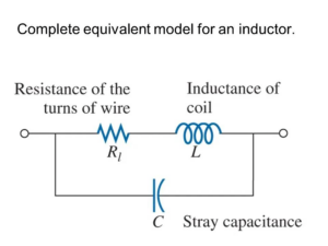
Electronic components in the real world never behave in the perfect, idealized way that basic circuit theory might suggest. For example, an inductor isn’t just a pure inductance – it also has resistance, capacitance, and other complex electrical properties that affect its behavior.
Every component placed in series with a speaker creates additional impedance. This added impedance not only decreases the damping factor as previously discussed but also directly reduces the signal strength reaching the speaker.
This impedance restricts current flow – the higher a component’s impedance, the less current can pass through. Consequently, the speaker requires more power from the amplifier to achieve the same volume level. In systems with particularly complex crossovers, this can dramatically reduce the speaker’s sensitivity (efficiency), often necessitating much more powerful amplifiers than would otherwise be needed.
All these passive components consume power that never becomes sound – instead, it’s wasted as heat. This represents a direct loss in system efficiency.
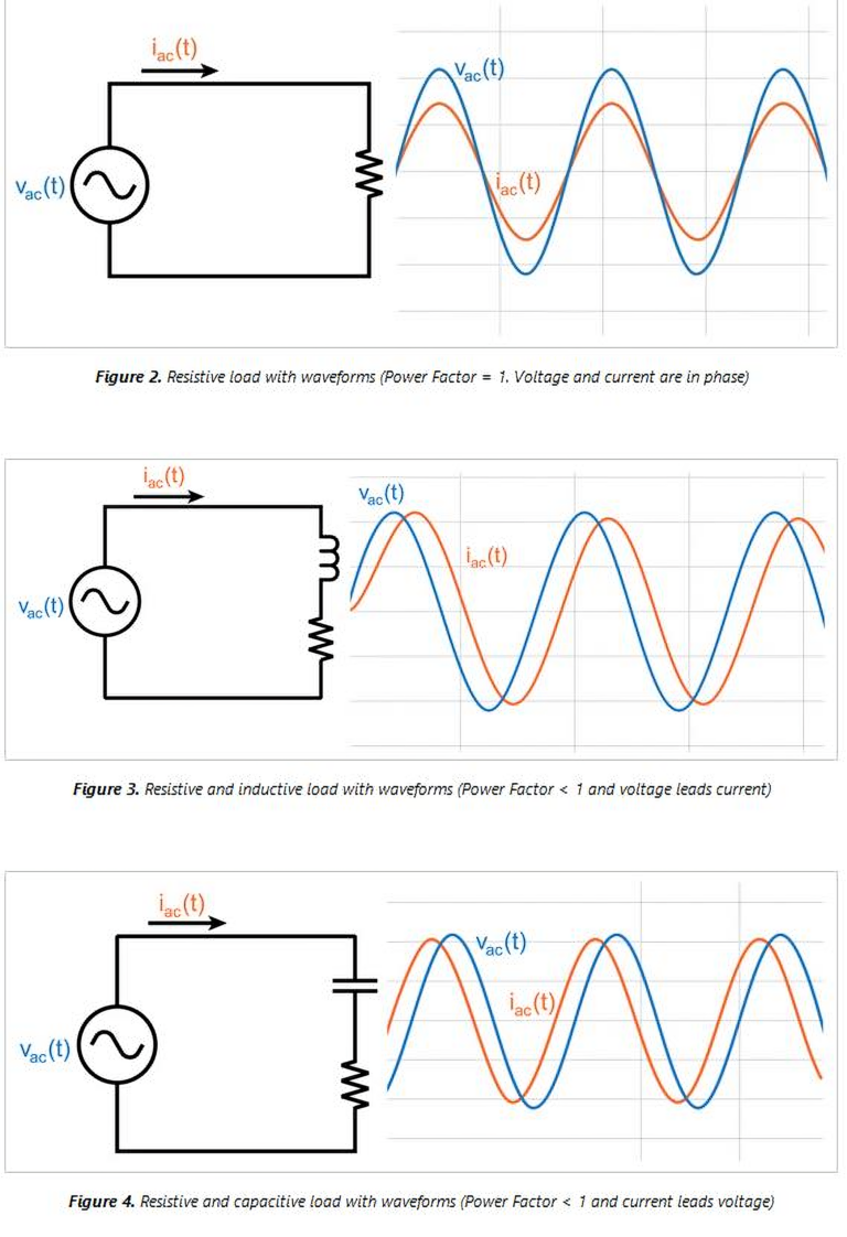
There’s also the critical issue of power factor in AC circuits. Effective power in alternating current systems depends not just on voltage and current magnitudes, but also on their phase relationship – ideally, they should rise and fall in perfect synchrony. When a passive crossover is added, it shifts this relationship, causing voltage and current to be out of phase with each other. This phase misalignment creates a substantial loss in effective power reaching the speaker, further reducing system efficiency.
Furthermore, the final output power no longer has the same shape as the current and voltage, and again results in a distorted signal.
Conclusions
Probably a book would be needed to deal in detail with all the defects and problems induced by passive crossovers in the audio field. However, what we can draw from it is that in an audio system, passive crossovers are the real weak link in the chain, even though the speakers already have strong non-linearities and high tolerances.
It should be noted that the problems of passive crossovers are also encountered in specific types of active crossovers, such as phase shift and added noise.
It must be remembered that there are two types of active crossovers: analog and digital. Digital active crossovers work by cutting and reprocessing a digital signal (before the source, if this is a DAC, or between source and amplifier if this is an ADC-DAC). Active analog crossovers, on the other hand, act on a purely analog signal before it enters the power amplifier.
Active analog crossovers suffer almost from the same problems as passive crossovers: they do not damage damping and do not create response artifacts, but they have tolerances, have distortion problems, have phase rotations, change performance as the temperature changes and they also suffer. of memory distortion.